Trench design for new developments
Our aim is to develop solutions that retain large volumes of stormwater in the landscape to support the urban forest.
This design is for use in nature strips of ‘typical’ suburban streets in new developments. It addresses two problems with individual systems, which:
- are costly to maintain, and
- capture small volumes of runoff.
As an alternative, our design:
- uses one inlet to serve multiple trees, and
- has a system/catchment area ratio of 10%, plus an internal water storage.
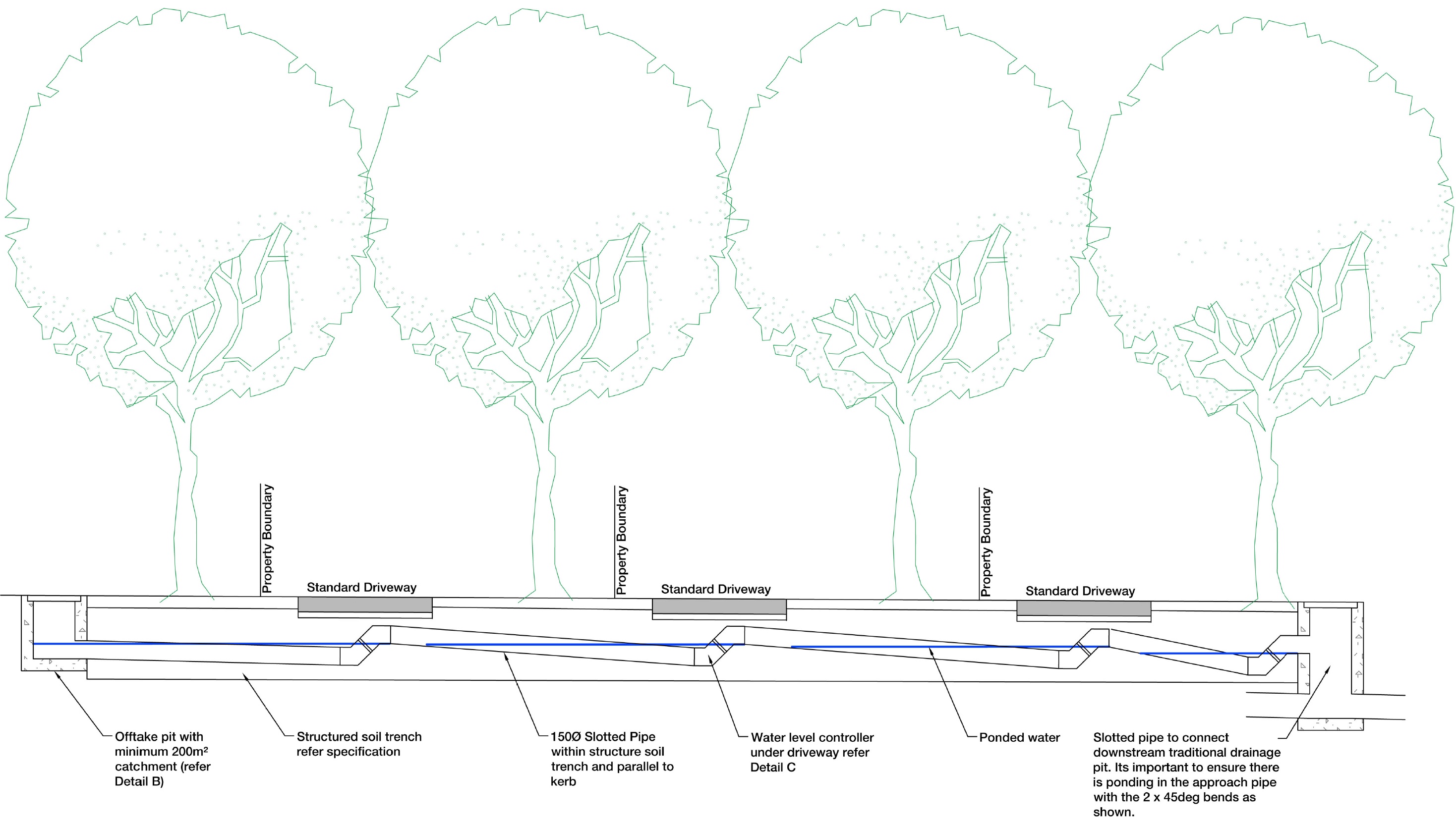
Description of design
Key elements of the design are:
- an inlet pit which intercepts runoff upstream of a standard drainage pit
- the inlet pit can be designed with a grate to exclude gross pollutants and a sump to collect sediment
- flows are conveyed via solid pipe to a structural soil trench, offset from road infrastructure and below-ground services
- the structural soil trench runs the length of the road, including under driveways, ending at the next downstream standard drainage pit
- slotted pipe in the trench promotes exfiltration into the surrounding soil
- an internal water storage in the structural soil trench is created by connectors spaced according to the slope of the road
- the slotted pipe connects to the next downstream drainage pit with a jump-up connection
- the design has built-in redundancy where, in the case of blockages to the catch pits, flows will be conveyed to side entry pits as before.
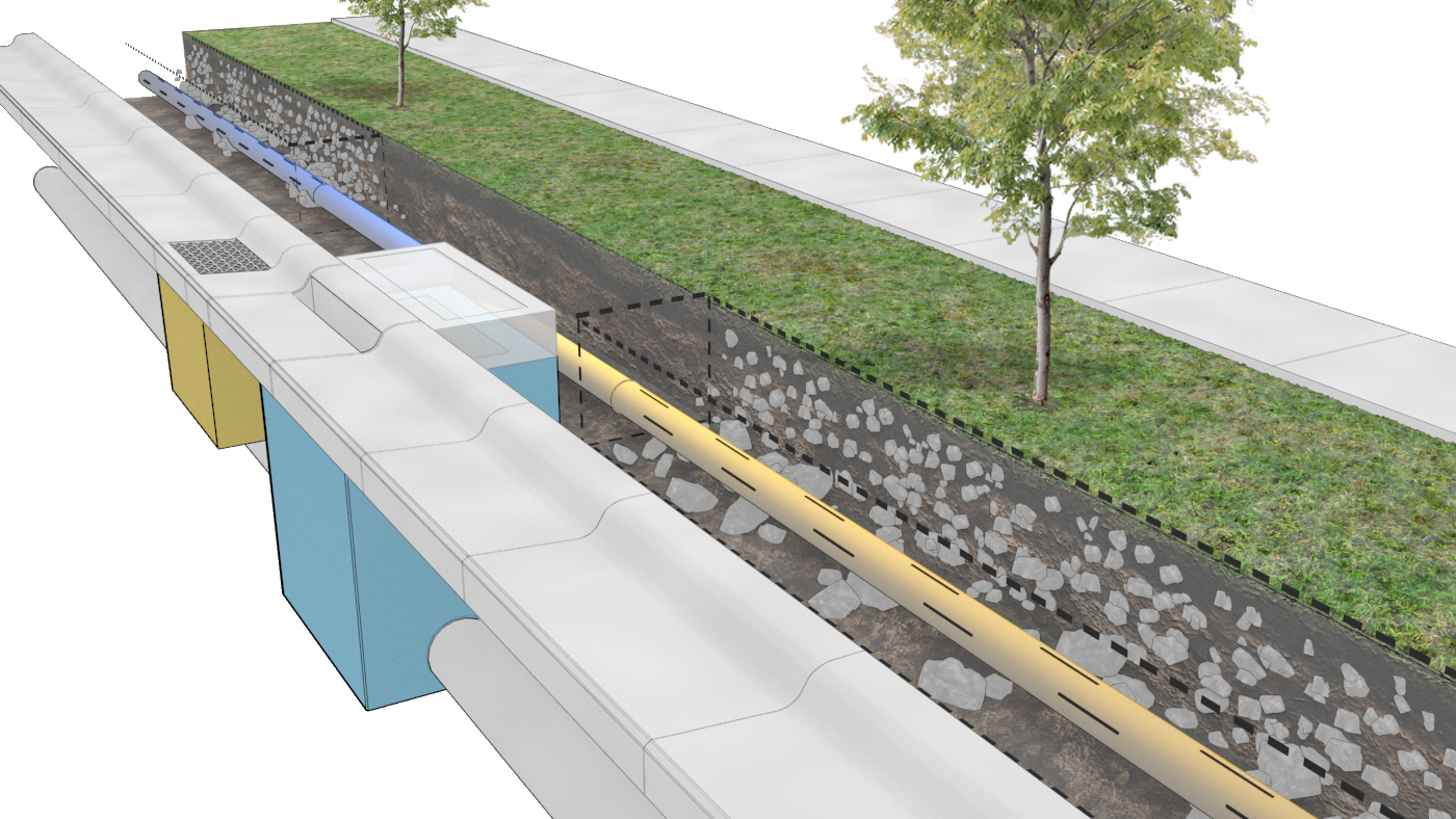
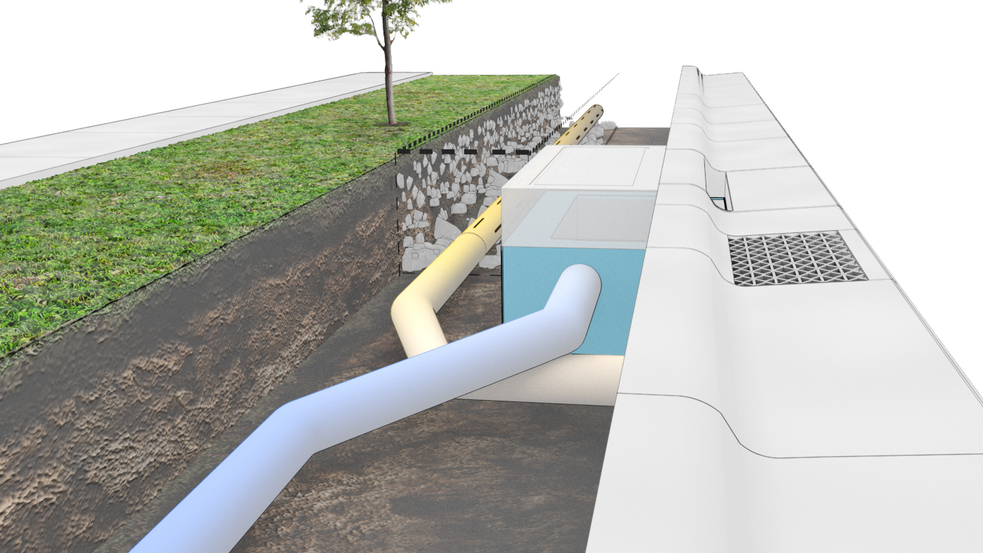
Interacting pits and pipes
Links to the standard drawing are below, but we find the 3D representations below a useful way to communicate.
Feedback
We hope to develop this drawing to the point where it can be integrated into standard practice, e.g. in the Engineering Design and Construction Manual for Subdivision in Growth Areas.
Although we have solved some problems with this design, no doubt we have created new ones and overlooked other requirements.
We need your feedback — please download and annotate the PDF and/or CAD file below and email your ideas to Chris Szota.
We’re working on some practice notes and will upload very soon.
Pilot sites
We’re testing this design at the IYU Carpark in Pakenham, but it’s intended for use in streetscapes. If you’re a developer or working at council and are keen to work with us to test this design in a new development, please get in touch with Chris.
Project team
This standard drawing represents a collaboration between Cardinia Shire Council, Melbourne Water, Afflux Consulting and researchers from The University of Melbourne. This work is was made possible through a Liveable Communities, Liveable Waters grant.